|
|
|
| |
|
Component Based Software Development Paradigm
|
|
|
Many software experts believe that an innovative software
component paradigm or CBSDF (Component Based Software
Development Framework) has great potential to solve
‘Software Crises’, the term coined to describe,
development of software projects taking too long (or
miss schedules), poor-quality, far exceed budget, not
work very well or even end in failure. Countless research
efforts have been underway for decades to find an ideal
software component paradigm.
|
|
|
SECTION#1:
Plug-n-play Components are essential to build True Component Paradigm
|
|
|
To build TRUE component paradigm, we must invent plug-n-play (or "loosely coupled")
components. To build an automated assembly line, one should first create ready to assemble and
easy to disassemble (or plug-n-play or replaceable) components. For examples, ready to assemble components for
the cars are Engine, Gearbox, Battery and Seats, which are manufactured elsewhere; and assembled
on an assembly line. But, the ingredients such as steel, rubber, plastic and leather to make
those loosely coupled parts are not ready to assemble plug-n-play components. Such ingredients
are tightly coupled and very hard to disassemble to replace them. They may never be used as
'replaceable' components and hard to be use in an automated assembly line.
|
|
|
Likewise,
to build a TRUE component paradigm for the software
applications, we must define what is the ideal replaceable component for the software, and create elegant processes to
manufacture
such replaceable components. (You may click
here for an example). This plug-n-play
components are also refer to as loosely coupled
replaceable components. Then invent automated or simple mechanisms to integrate
(or couple) the loosely coupled components. Also it is even more important to
remove (or decouple)
the components for easy maintenance of the application, for example, if
the components need to be independently refined or replaced to meet the evolving business.
|
|
|
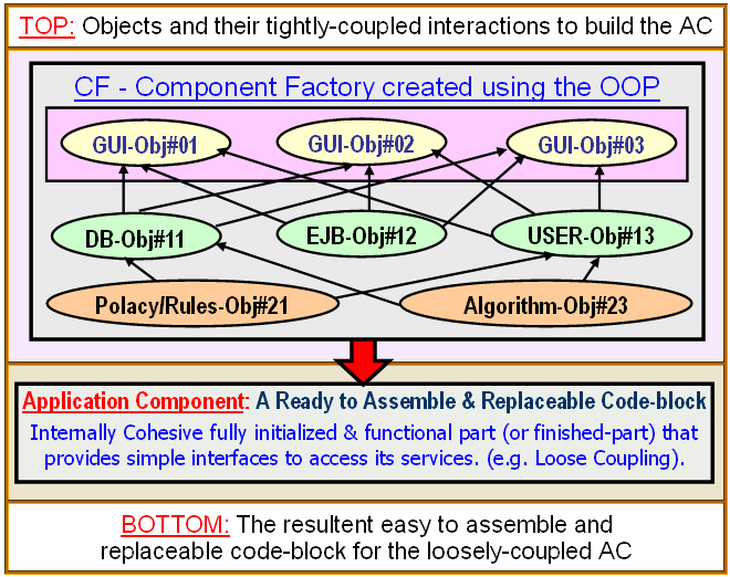
Today’s understanding of
software components is insidious and Fundamentally flawed
(Extremely Important Proof).
It may be impossible to use such components as plug-n-play components.
For example, today's components shown in the top-part of figure#2, such as, EJB (to get data,
define business rules, policies, supply-chain or dataflow
algorithms) only supply business logic (or application
logic) part for the plug-n-play application-components.
On the other hand, presentation or GUI components such
as reusable GUI classes for Charts, Maps, Meters, Trees and GUI-controls (ex.
Lists, menus, Dials, and buttons etc.), define presentation
templates and only supply presentation logic part for
the plug-n-play application-component.
|
|
|
Let me repeat the manufacturing analogy, it is hard to build
an automated assembly line that can use casting-moulds (e.g.
casting, lathe machines forging or moulds to shape the
metal) and the raw metal or ingredients (that will be shaped into the
part). The automated assembly lines mostly need loosely
coupled finished-parts
, which are custom made in factories elsewhere, to meet the given
specifications (e.g. very simple loosely coupled interfaces, which are easy to
assemble/disassemble - please
click here to learn the essential properties of loosely coupled components).
|
|
|
Figure#1 |
|
|
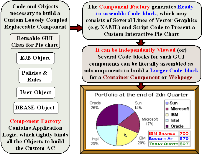
Now
lets come to the software parts: consider a
simple example, a Pie chart for an application.
One could create a pie chart finished-part
using a reusable Pie-chart class. The reusable Pie-class is
nothing but a template or a mold, which contains
necessary logic (or recipe)
to present a pie chart component (for the data
inputted at run time). Each reusable GUI class acts more like a mold that
creates a component.
One writes code to access
database or may use reusable EJB to get data. Then
writes code to initialize a Pie-chart object using the
data, to present the finished pie-chart component in
the application. In this case, the Pie-chart class
clearly acts as a mold (or a template) to mold the
data, and the data is the ingredients to make the
final part. Therefore, neither EJB nor pie chart class
can be ideal plug-n-play components for the
application. All the Objects, config-files and logics (e.g. business logic) are
tightly coupled to make a "Custom Component". In general, the Component
factory may use one or more GUI Objects and other data objects (as shown in
the top-part of Figure#2) to create custom loosely coupled component
(Bottom-part of Figure#2).
|
|
|
Figure#2 |
|
|
Those
traditional components are used as ingredients or tools,
and manually hard coded (i.e. tightly
coupled) to merge them to build the application component.
Therefore, they are just ingredients used to build ready to use
final or finished-parts for the application. The resultant component is a finished
replaceable part, which may be run
independently as a webpage or applet. One may loosely couple many such
independently executable applets (i.e. replaceable parts) to build an
application (see the following figures).
|
|
|
Any research focused to improve traditional reusable components (i.e. EJB,
GUI or such libraries/API), might allow one to build
better ready-to-assemble final components, since, better
ingredients would help us build better products for
less and faster. However, those components (the ingredients
for the replaceable parts) themselves may never
be able to become "ready-to-assemble &
easy-to-replace ” loosely-coupled parts for the application. Analogous to better
ingredients such as steel or composite material may
allow us to build stronger, lighter and better automobile
components for less, but the bare metal sheet can rarely
be used as an interchangeable part on the assemble line.
|
|
|
Note: Most software researchers call them
(i.e. EJB/GUI-Class) components, which we feel are just ingredients for the REAL
components. Since
the word for "Component" has taken by them, we call our components "Loosely coupled
components" (AC in short). So please
do not confuse between their "Components" and our new kind of "Components",  (as some comedy characters in movies/TV confuse for word Indian, between native-Americans
& Asians Indians
(as some comedy characters in movies/TV confuse for word Indian, between native-Americans
& Asians Indians ).
Please see the 3D-figure below and decide, which one do you think is Better or Real Component
(i.e. their EJB/GUI-Class or ).
Please see the 3D-figure below and decide, which one do you think is Better or Real Component
(i.e. their EJB/GUI-Class or  Raju's AC)?
(Please see Appendix below) Raju's AC)?
(Please see Appendix below)
|
|
|
True component paradigm can be built by:
|
|
|
(i). Define characteristics of true plug-n-play components,
such as functionality, services and clear interfaces;
especially must
be decoupled (or untangled code) and have clearly recognizable
boundaries to be programmatically or automatically plug-in
to (or out of) the application code, to independently refine/update or to replace by a newer component at
any later date. (ii). Create simple processes to manufacture
such plug-n-play or finisher-parts, each of which custom build
to meet each user/application’s unique functional
needs and interfaces. (iii). Invent elegant and intuitive
mechanisms to automate the integration (e.g. simple
semantic integration, or CASE tools) of such components,
which is the necessary
condition for a true component paradigm. This
web site briefly summarizes those processes and mechanisms
and also illustrates them using simple examples. The
inventions are far broader than the simple illustrative
examples given.
|
|
|
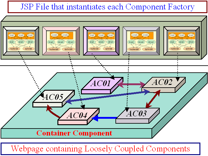
Figure#3:
Each GUI Component is placed at Proper Location |
|
|
Arrows
Represent Loosely Coupled Service Interfaces
If the Loosely Coupled Components (e.g. AC01 to AC05) need to collaborate with other,
they interact with each other by requesting each other services at run-time
(Note: Each component is fully created finished-part
and could run independently)
|
|
New
kind of perfect Loosely Coupled Components
(Click on above to learn about
the Component Making/Packaging)
It requires just 2 lines to include each
CF in JSP for an AC. If
any two ACs needs to collaborate with each other, on average they need 3 to 5
more lines of communication code (e.g. to loosely couple service-provider and service-consumer
ACs).
|
|
Figure#4
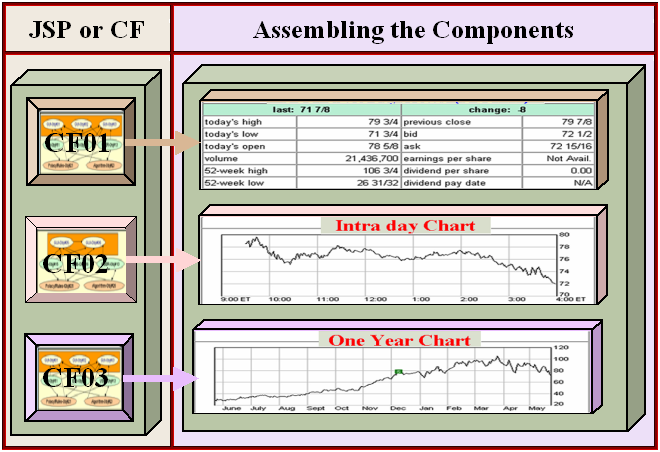
As
shown in above FIG1&2, CF Class encapsulates the tight
coupling of all the Objects and all the logics (e.g. Application,
presentation & business logics). It needs just 2 lines of code to
include/replace an AC from webpage. If any two ACs
needs to collaborate with each other, on average they need
no more than 3 to 7 lines of communication code (e.g. to loosely couple
service-provider & service-consumer ACs).
|
|
Appendix:
What Constitutes a Real Software Component
If the basic theory and assumptions are flawed, any attempt to explain the phenomenon
observed in the real world always end up with unexplainable exceptions and
inconsistencies. For example, few centuries ago physicists assumed that earth was the center of the universe. Hence, it became impossible to explain the planetary
motion they could
observe in the sky or to predict/calculate their motion.
History repeats again for the software components. It looks like every one has a definition for what constitutes a software component. There are numerous definitions for software component but none of them could provide consistent picture and explain how they could be comparable to the REAL interchangeable components (e.g. Hard-drive, CD, Network-card or
car-battery).
Trying to understand software components and engineering, with out understanding the critical loosely coupled property, was like the fabled blind men groping an elephant and defining
it (e.g. by grasping one aspect such as component reuse).
The component engineering
of the physical products (e.g. Cars, Computers) is mainly based on two essential characteristics
of the ideal component: (i) Loose coupling,
so that the component can be easily assembled, and also easily disassembled to remove/replace. (ii)
Ability to build Component hierarchy, which
is leveraged to effectively distribute the complexity of each large or complex component among many smaller independently designed
and built 'loosely coupled' subcomponents. For
example, computers contain many plug-in Cards (e.g. Network, Graphics),
which in turn created by assembling loosely coupled Chips, and so on.
Hence,
we think 'hierarchies of swappable
module' is ideal component based framework. In every aspect, the AC has better characteristics than most
physical interchangeable components like Hard-drive, CD-player, Network-card and
Car-battery. (i) Building hierarchy: Designer of a
larger AC could use other ACs as subcomponents (e.g. FIG.4).
Another AC could use the
larger AC as a subcomponent. (ii) Loosely coupled: AC can be included/replaced in minutes as a block (or
by changing 2 to 3 lines). If the AC needs to collaborate with other ACs, it could communicate with them trough simple loosely coupled service
interfaces (3 to 5 more lines of coupling
code). AC is internally consistent highly cohesive code-block,
which could run independently (e.g. as a CD-player or Car-battery to get its services).
|
|
|
|
Note:
A definition for ideal software components must be same as or similar to the definition for
ideal physical components (e.g. Hard-drive, Network-card, Graphics-card or IC-chips that are used as subcomponents in the
cards to build component hierarchies). I couldnt find a definition for the physical components. It
may be not necessary because, when we see one we could easily recognize it. Why should the "software components" be any different?
Almost every one
also instinctively recognizes
a software component, when he sees a component (e.g. Chart, Table, Dial, Shopping-cart/Invoice, Tree or a Flight in Air traffic control), in
the GUI applications.
Is there any other word to call them (e.g. Table or Chart in Right side of Fig#4)? There is no room
for doubt or debate (Rest
My Case!). They are not likely be Objects. If
the OOP is used, they may be created as shown in the above FIG-1&2. Or may not use
the OOP at all (e.g. if they are created in JSP/SVG/HTML/EcmaScript/Ajax). Also almost all of them are loosely coupled or not coupled at all.
Almost all software applications are full of components, but none of the
applications are designed using proven component engineering principles and
processes (e.g. Loose-coupling & Component
Hierarchy). Ironic ... Isn't it?
In a TV documentary on making a Ferrari car, I heard that its engine has about 800 components. If it has an electric wire, I am sure it is counted as one component and not two (i.e. Copper-wire inside and plastic insulator outside). Hence, laymens terms: a component is nothing but a loosely coupled part, which can be
both easily assembled and
disassembled. Also please recall our comparison of component hierarchy in a
CBSD application and for a one-of-a-kind computer system. Any of the components
(See boards 1, 2, 3, 4, and 5 in Figure#5) in the hierarchy can be removed or replaced quickly.
|
Figure#5:
Structure &
Hierarchy of the Ideal Components
|
 |
 |
|
Sample
Computer Board
|
Sample
CBSD Application
|
Isn't
it commonsense and don't we already know that the ideal component for cars and
computers are loosely coupled. Many are
assembled as subcomponents to build component hierarchy?
Every container component encapsulates all its subcomponents and it is loosely
coupled (hence easily replaceable). Also when a container component is removed all its subcomponents are effectively removed without leaving any fragments
to cause bugs.
|
|
|
Definition
for "What constitutes an Ideal Component?"
An ideal component must have the following important characteristics. Loose
coupling: The component must be easy to assemble and also easy to dissemble to remove or to replace.
Must allow building
component hierarchy: Each component may be created by assembling loosely coupled subcomponents.
Each component can be used as a loosely coupled subcomponent in yet another large
loosely coupled component, and so on. When such large component hierarchy is created, each of the components in the
component hierarchy must retain its
loosely coupled characteristic.
|
|
|
Conclusion:
Broadly speaking, component is a part of a system. Software components include: Methods, Class-definitions or
Modules within the applications. A hardware component for a computer can be a device as small as a transistor, silicon or as large as a disk drive (may contain many devices made of
silicon/CMOS). One-of-a-kind products (e.g. experimental computer or spacecraft)
use many non-reusable one-of-a-kind loosely coupled
parts and their hierarchy.
All the other things being equal in designing on-of-a-kind product
(software/physical), the above two
most coveted characteristics of the physical
components, which are missing for
today's software components. If it is not possible to build loosely coupled
parts and the hierarchies, the makers of physical products face problems no different than
the software makers.
Of course makers of one-of-a-kind components (software or hardware) could employ highest possible reuse to make the custom one-of-a-kind loosely coupled component.
For example, the designers of one-of-a-kind components (e.g. Computer
Boards/Cards) could use many off-the-shelf devices. Likewise, the software component factory
(See above Fig.1&2) could maximize the reuse by employing pre-fabricated
libraries such as GUI and EJB.
Please
Note: Although
some pages in this website discourages
research on reusable pre-fabricated components, Pioneer-soft is not against reuse. In fact our earlier thrust to create the most flexible GUI-API
in order to maximize the reuse led to the invention of the loosely coupled parts. We believe the loosely coupled component based process maximizes the reuse. We only advocate employing right balance and there is no need for sacrificing one for the other.
|
|
|
SECTION#2: Brief Summary & Overview of the CBSD Process
|
|
|
The
following figure#1 (in this section below) shows the
main difference between the traditional application
development process and our software Component paradigm
(or our CBSDF). Today developers create the application-component.
To reduce their coding effort (or automate certain sections
of the code), application developers use reusable
components (or Class libraries/API for GUI-Controls,
Menus, Meters, Dials, Charts, Trees, Maps and EJB etc.)
in the code for the application-component.
|
|
|
Then
the Application-Components are integrated to build larger
and larger Application-components. The developers required
to manually hard code the integration code to build
the larger component. The manual integration-code tangles
the code for the application-components to fit, and
they are welded into the application; hence they are
no longer independent or interchangeable. In this process,
it is not possible to preserve the independence of the
Application-Components and very hard replace them.
|
|
|
|
|
A
brief definition for a very important new term: Application-Component
or AC (a finished-part).
Many applications use graphical-components to simulate
(or model) real environments and interactions of real
objects. Applications may model real-time Visual simulation
of dynamic systems and environments, such as real time
Weather patterns, geographical-features, Air-Traffic
control systems and decision support or real time data
analysis systems. Consider an application that displays
moving taxis on a vector based city map. The map and
taxis must be redrawn frequently, since taxis are rarely
stationary. Also, it should depict many pieces of data
and states such as vacant, location, occupied or unavailable
etc. In this application, an AC could simulate (or represent)
the taxi (a cab).
|
|
|
The
AC not only contains code to present the information
and states of the taxi, but also contains code
for service methods,
which could be used by external code (or other ACs)
to interact with the ‘taxi’, for example,
to change its state or get its data etc. Also, functions
in the AC supports mechanism for the external code/ACs
to register event notification
methods or callbacks (e.g. state change, data
arrival or events, such as, mouse click etc.), each
of which will be called upon the event.
|
|
|
For
another example, Power-grid or plant operators deal
with many simultaneous measurements and controls that
require frequent, expert attention. Here, the operator
interacts with GUI-components (e.g. dials, sensor-tuners,
measuring meters or scales etc.) in order to control
or to change states. An AC for Dial-Control contains
code, not only to display reading of current setting,
but also provide service methods to register external
callbacks. If operator changes the setting of the Dial,
it calls the callback to notify the change and provides
value of the new setting or parameter. Other sample
AC, such as a temperature measurement-meter could not
only contain code to present current temperature, but
also support service methods, which might be used by
external code (e.g. other ACs, embedded-device-driver
for the power plant meter) in order to update the temperature
changes etc.
|
|
|
It is extremely important to understand the difference
between the GUI-component (e.g. a reusable Class-API) and the AC. The AC is a cohesive Object-instance (an
fully initialized and self containing instance – a finished-part)
- a code block, which encapsulates entire component dynamic functionality and interactivity. It contains
code to present the Component; and also functions, such as, services, event handlers (e.g. user events, data
arrival and state change) and methods that facilitate external code to register Callbacks to be notified on
given events.
|
|
The
CBSDF-Paradigm needs developers to write code to create
Component-factories
(“CF” or also referred as ACCG-Application Component Code
generators). The CF encapsulates presentation-logic and business or application-logic; and generates custom
AC (fully functional code block). The AC may be custom created by the CF, for the application
using business logic (or application logic and other concerns, such as, user profile, security and platform
etc.) to meet the unique needs of the application, such that it supports a specific part/component (or an identifiable
feature of the application). |
|
|
Furthermore,
the AC’s code contains service functions, which
may be called to request the Component’s services
and to register callbacks etc. Besides generating the
AC, CF also supports the following methods:
|
|
|
To
get the information about the AC’s services. This
information may be used generate code in the web page,
in order for other ACs to access its services.
|
|
|
To set information about services of other
ACs, which may be used by the CF to generate the AC’s
code, such that, the AC call the methods to get the services of other ACs.
|
|
|
|
|
The
CF may use pre-build (or re-usable) class libraries,
(e.g. GUI-API Java-Classes for GUI-Controls, Dials,
Trees, Maps, taxis, Charts, etc. Process to use these
Class API (e.g. Java classes) is not very much different
from the way traditional applications use class libraries
for Microsoft’s Windows GUI-Controls and Charting-Controls
etc.; (which is briefly illustrated in the next section).
The CF may use one or more GUI-classes to generate the
code for the AC (or it’s subcomponents) that presents
the display-component. The CF tightly couples the application
logic and the presentation-logic (e.g. GUI-classes),
where each GUI-class generates the presentation code
(e.g. SVG or XAML) for its subcomponents.
|
|
|
Note:
We have used Java on the Server and W3C’s SVG
on the Client for this proposal. But, one could also
use others technologies, such as .NET/C# and XAML/C#
respectively. This kind of AC may be created for any
XML graphics languages (e.g. X3D, DHTML).
|
|
|
The
CF could easily be designed to generate the code for
the AC, such that, it is a cohesive and contiguous
block of code to present the component, which also supports
rich set of features and methods, such as Callbacks
and Services for external code in the application.
These methods could be used to access the AC’s
services by external code or other ACs. These ACs could
easily be programmatically integrated to build larger
and larger components and so on.
|
|
|
It
is possible to create larger CF, which uses many GUI-classes
or CF (i.e. Independently build & tested Java Classes)
to build its sub-components (or sub-ACs). Each CCG (GUI-class
or CF-class object) may be instantiated and initialized
with in the larger CF, or externally and passed/input
to it using set methods. They dynamically generate a
customized sub-AC (or subcomponents or finished-parts)
respectively. The larger-CF further interacts with them,
to obtain necessary information (Ex; Services, Trigger
or Callbacks etc.) about the Application-Components.
The larger-CF uses the information to integrate all
the “parts” (i.e. subcomponents) to build
container AC. |
|
|
Please
note the bi-directional data exchange between larger-CF
and the CFs. The bi-directional communications are,
mostly nothing but, simple get-set methods of the Objects.
The larger-CF may not contain actual integration code,
but contains ‘recipe’ (or integration-logic,
which is often few lines of very simple code, which
interacts with sub-CF based on their generic class interfaces),
which generates the code to glue (or to loosely couple)
all the sub-ACs, so that all the ACs could collaborate
(or communicate) with each other. This entire process
is simple and elegant as briefly presenter in later
documents. Any CF may be used by another CCG to create
its subcomponent. This simple loosely coupled process
can be repeated to build larger and larger components. |
|
|
Summary
In Simple Terms: The CF generates custom AC at
real-time based on each requesting user’s profile
and platform. The code for each AC can be created in
a “contiguous block”.
To use the AC as subcomponent, we may copy its “code-block”
in to the code for the container-AC (Fig#1). The container-AC
may contain many sub-ACs, whose code may be copied usually
in any order into the code for the container-AC. This
process can be repeated to build larger and larger ACs
(Fig#2). We may invent many simple or automated mechanisms
to integrate (or couple) the AC and its sub-ACs. |
|
|
|
|
|
|