| Loosely Coupled Component Based Software Development Process |
|
|
Process to Loosely Couple components to build a large component (or application) comprises of methods: (i) Compose one or more components to build a larger component. (ii) Subsequently the larger component may be used as a subcomponent to build yet another larger component, and so on.
|
|
| Brief definition for the terms “Loosely Coupled Components” and "Component Factory": |
|
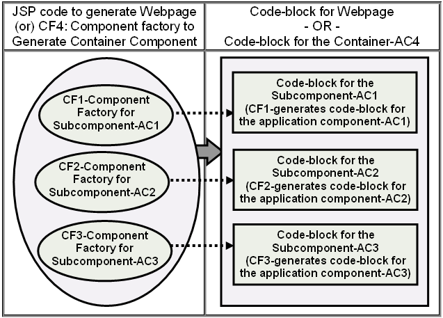
For example, the pseudo code listing shows a sample process to build a “ Component factory” for a larger component by composing subcomponents. One or more subcomponents for the larger component (or a web page) may be custom generated by their respective CFs. The CFs for the subcomponents are properly instantiated and initialized or passed by reference to the code for the larger component, as shown in figure#1. |
|
|
Pseudo Code Listing#1: Container Component Example#1
|
<TABLE>
<TR><TD>
<% // Instantiate & initialize the CF for the subcomponent
AgileTemplate CF1 = new CF_Subcomponent_A(user_data, env_data);
CF1.CGM(out); //Get & Write code-block for
subcomponent-AC1
%>
</TD></TR>
<TR><TD>
<%
AgileTemplate CF2 = new CF_Subcomponent_B(user_data, env_data);
CF2.CGM(out); //Get & Write code-block for
subcomponent-AC2
%>
</TD></TR>
<TR><TD>
<%
AgileTemplate CF3 = new CF_Subcomponent_C(user_data, env_data);
CF3.CGM(out); //Get & Place code-block for
subcomponent-AC3
%>
</TD></TR>
</TABLE>
|
|
Reusable Container Component Example#2
|
// The references to Component factories (e.g. CF1, CF2 and CF3) may
// be passed to build subcomponents for a reusable GUI-component.
// For example, their references may be passed to a Rotate-banner:
AgileTemplate CF_List[] = { CF1, CF2, CF3 }; //Build an Array of Components
AgileTemplate RB = new RorateBanner(CF_list, 3); //Build Component-hierarchy
|
|
|
|
The subcomponents are placed in the container component (or web document) and not yet coupled (i.e.
no coupling code is included, hence they might not be able to communicate or exchange data with each other). Hence, they have
no dependency on any other outside components or between them. This step is kind of like placing physical components like a light bulb, a battery and a switch in a package
(e.g. torchlight) and turn on the switch. Nothing happens, until the following step is completed: coupling the components using few wires.
(Click here for brief summary and an example for "Loosely coupled systems")
|
|
|
|
|
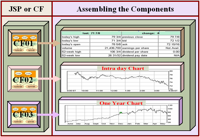
Figure#1A (Above) & 1B (Below an Example)
|
|
|
|
|
|
|
|
The pseudo code in the listing assembles the replaceable
code-blocks for the subcomponents, for example, to show the subcomponents at proper locations. If the subcomponents need to collaborate or exchange data, they must be coupled. Any
component coupling methods, such as, the ones discussed earlier may be employed to couple the subcomponents. For example, “integration-logic” or “publish-and-subscribe” method may be used to couple service-providers and
consumers components. Please refer to figure#3 and Figure#4.
|
|
|
Figure#3 |
|
|
|
|
|
Figure#4
|
|
|
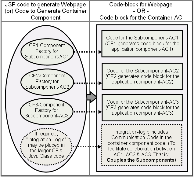
The Integration process couples the subcomponents in the container component (or web document). This Integration process “Loosely Couples” the subcomponents. Well-designed application components (i.e. AC) minimize the code required to couple the components (e.g. accesses its services). Hence, it requires minimum effort to integrate the “Loosely Coupled” AC. On average, it may require 4 to 10 lines of simple Integration-logic code to integrate a large AC.
|
| |
|
The larger CF requests each of the CF to custom build its subcomponents (e.g. based on user preferences and privileges at real-time). The “Component-factory” dependency may be shown as in the
figure#2 and figure#5. It is analogues to manufacturing supply chain, where the subcomponents are dynamically selected and custom-made
by respective component-factories and delivered “just in time” to assemble the product.
|
|
|
Each GUI Component is placed at Proper Location |
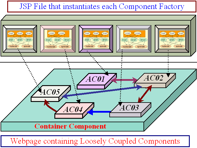
|
|
Arrows
Represent Loosely Coupled Service Interfaces
If the Loosely Coupled Components (e.g. AC01 to AC05) need to collaborate with other,
they interact with each other by requesting each other services at run-time
|
|
New
kind of perfect Loosely Coupled Components
(Click on above to learn about
the Component Making/Packaging)
It requires just 2 lines to include each AC (as shown in the listing#1). If
any two ACs needs to collaborate with each other, on average they need 3 to 5
more lines of communication code (e.g. to loosely couple service-provider and service-consumer
ACs).
|
|
Each AC is an independently executable module (or code block). A container component is created by putting many of them together.
If some of them dont need to collaborate with each other, they wont have
any couplings. If they need to collaborate, we need to include few lines of code
to couple them. The solid-arrows in the above figure shows the dependencies (or loose couplings) between the components.
|
|
|
|
This general process can be used to create any larger “Component factory”. This container-component (i.e. AC) in turn may support one or more services for other components. In that case, it’s “Component Factory” (e.g. Java Class for CF#4) need to support get-methods for the integration-logic to get the names of the service functions. Now yet another larger CF may use this CF to build a subcomponent for its component. That is, another CF may request the CF#4 to custom build a subcomponent for its component, as shown below:
|
| |
|
AgileTemplate CF4 = new CF_Subcomponent_AC4(user_data,
app_data);
|
|
|
The “integration logic” of the said larger CF might access the names of the services of the AC4, using the get-methods of the object “CF4”. This process of building Component Factories that couples one or more subcomponents (each of the subcomponents may be created by another component factory) to build larger components might be repeated to build larger and larger components as shown in the following figure:
|
| |
|
|
|
Figure#7
|
| |
|
The main advantages of this process are: the application is literally assembled by using outstanding
Replaceable-Components: (Please
click here to review the proof, why replaceable
components are the only TRUE components).
|
|
|
1.
|
The ACs are loosely coupled to the other ACs. Hence, it requires minimal effort to remove each AC; or replace each AC with “functionally-equivalent” new AC. For example, if one likes to replace any AC (in the application on the right-side), he may replace the old-CF by a new-CF.
|
|
| |
For example, steps to replace (or
Replace AC-15 with AC-25) the CF#15 with CF#25 (where AC-25 of CF#25, may support improved interactivity or provide more information):
|
|
| |
|
Find the location, where the following statement present in CF#19:
AgileTemplate CF15 = new CF15_Subcomponent (user_data);
|
|
| |
|
Substitute the above statement with the following statement:
AgileTemplate CF25 = new CF25_Subcomponent (user_data);
|
| |
| |
|
|
Now, please find all references to the CF15’s object in the CF#19’s Java class (for example,
'Integration-Logic' or IL" may be accessing data from the object to integrate the AC), and make necessary changes to the
'IL' code. Since the AC is Loosely coupled, the IL may refer the CF15’s object in 2 to 5 lines of
code (e.g. to couple the services between two collaborating components).
|
-
Replaceable-comp[onents: removing
or interchanging/replacing any component is simple and straightforward
process, needs just few minutes.
-
Independently-reconfigurable-Parts:
Please also notice that each CF-Class could easily be independently redesigned
to meet evolving business needs.
|
|
|
2. |
The AC encapsulates all its sub-ACs. This is one of the major advantages of our framework over Object-oriented
process (the third essential
property for the loosely coupled parts). When one removes the CF15 (on the left-side), it effectively removes the AC15 and all its sub-ACs (e.g. AC8-AC13 with out any
trace).
In the traditional OOP applications, If the component is large and contains number of subcomponents, it is practically impossible to remove
the component.
|
|
|
If you need to replace an hard drive in your PC, are you going to open the PC and chip away one subcomponent (i.e. device) at a time? No! just unplug the Hard Drive. All the devices are packaged with in the Hard-drive casing and they go away with the casing. The CF/AC for each loosely coupled
interchangeable component offers the comparable encapsulation/functionality (important-link
- to show computer-makers face crisis similar to the software-crisis, if
they also cannot build hierarchies of
swappable modules).
If
a physical product is build by
hierarchically
assembling swappable modules,
some time one may need to replace a container-part (e.g. engine) or some time
replace just a subcomponent
(e.g. piston, fan-belt or spark-plug). In the products, container-part
physically encapsulated its subcomponents. Top level parts (e.g. Battery
or CD-player) may be easer to replace. But it
requires lot of skill to replace subcomponent-of-a-subcomponent (e.g. pistons or AC-belt). Fortunately, in
the above CF supply chain setup, it needs about 5 lines to replace either a
top-level part (e.g. AC-15) or a deepest subcomponent (e.g. AC-09) (see
Fig#1 & #3).
|
|
| |
The CF/AC only have rational dependences and eliminates irrational
dependencies. A well-designed component based application should allow to remove any AC in minutes. Once all the CFs are designed and developed, one should be able to
assemble (e.g. build the supply chain) even large application in mater of hours. Simple tools may be able automatically detect the incompatible coupling between the ACs, for developers to fix integration bugs.
|
|
| Sample techniques to meet unique needs of the applications: |
|
1. |
The container-CF could use if-then-else (figure#5 below) to dynamically select sub-ACs. Each CF in the supply chain could dynamically select subcomponents.
|
|
2. |
The CF for the subcomponent custom builds the sub-AC, based on requesting user preference and profile. |
|
3. |
The reusable online-GUI classes can be designed to generate component presentation code based on requesting browser (e.g. Mozilla or IE6+) or (SVG or XAML). One just needs to update the GUI Classes to support future browsers or versions.
|
|
|
Please note that the CFs for the subcomponents may be
available on remote servers (e.g. as portlets; and the portlets
dynamically custom create the interchangeable 'code-block'
for the component). In that case, the code-block for the AC may be fetched using portlet’s URL and
user-data:
AgileTemplate RemoteAC = new Fetch_Remote_AC(Portlet_URL,post_data);
Remote_CF(Out); // Include the 'code-block'
|
|
|
|
| |
|
The CGI (e.g. JSP or ASP), which runs on the server, creates source code for the online applications (e.g. web document) by snapping together loosely coupled GUI components (FIG. 1). Then generates few lines of glue code to loosely couple components
(FIG.3 & 4). This glue code let the subcomponents collaborate with each other by requesting each others services.
|
| |
|
The application usually employees a CF ( "Component factory") to custom generate each component at real-time. The "CF" usually generate the component code locally, but it may fetch a mashup from a remote server, fetch from another application or read from a file etc.
|
| |
|
This simple process can be repeated again and again. For example, the CF contains code: (i). To
assemble 'code-blocks' of its subcomponents (which may be created by
another CFs) and (ii). Implements few lines of glue code to loosely couple each of the subcomponent.
|
|
|
Component Based Software Development Framework
|
|
|
Many software experts believe that an innovative CBSD (Component Based Software Development) Framework has great potential to solve ‘Software Crises’, the term coined to describe, development of software projects taking too long (or miss schedules), poor-quality, far exceed budget, and do not work very well or even end in failure.
|
|
|
Large information-technology or enterprise applications tend to be monolithic, bears a strong resemblance to many industries of the early 19th century--virtually all of the products are expensive, hand-crafted, error prone, one of a kind. The invention of
interchangeable components and assemble line paradigm revolutionized the manufacturing. Analogues to the product manufacturing, experts believe, invention of
software interchangeable-components and automation of their integration could revolutionize the software development.
|
|
|
Pioneer-soft has created working prototype, which proves that it is possible to achieve or even exceed the most of the goals set forth
by many researchers. The Objectives shall be achieved by designing innovative interchangeable-parts (also referred to as loosely-coupled plug-n-play parts).
|
|
|
What made industrial revolution possible is, standardized and “loosely coupled” components. Among other things, standardization defined few characteristics for the components, such as interface-requirements, that allow them to assemble with out any custom modifications at the manufacturing plant. Manufacturers called it out of the box assembling; and for software components this document calls it ‘Black-box’ integration.
|
|
|
The modern manufacturing has few other subtle yet powerful aspects/dimensions: One aspect is larger and larger component abstractions. For example, an automobile gearbox is a component, which may have been built by assembling many sub-components, purchased from other vendors. This gearbox in-turn is a part of the automobile power train (or engine). Yet another dimension of this component-paradigm is, that it offers choice (or options). Based on customer requests, at the assembly line manufacturer could choose from wide range of gearboxes such as automatic-transmission or manual-shift and number of gears etc. The same principles apply to all the other components, such as audio-system, AC, steering-system, computers, dashboard and car seats etc.
|
|
|
To emulate such intuitive and powerful manufacturing paradigm, an Ideal CBSDF shall not limit either the number of layers (or hierarchy) to build larger and larger components; or shall not limit the option to dynamically choose any sub-component at any stage (or layer). The dynamic selection and large supply chain of small (e.g. less complex) independently built “loosely coupled” custom-components substantially cut the complexity and costs of the large applications.
|
|
Although software development is different, confronts unique and complex set of challenges;
it is possible to create an elegant Component-Paradigm that emulates
such intuitive manufacturing-analogies and processes. This could be accomplished in a manner that
enhances the flexibility of the developer to meet wide range of unique and custom functionality needs of each application. |
|
|
|